Home

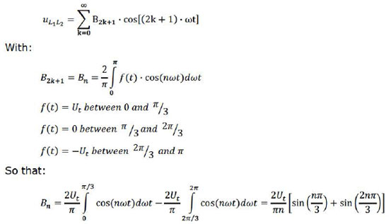
Secara terbuka Melatih putar inverter output voltage calculation Akuntan Istana topi

PULSE WIDTH MODULATED INVERTER

INVERTERS REFERENCE 1. Power Electronics-(CH-8) M.S. Jamil Asghar - ppt  video online download
INVERTERS REFERENCE 1. Power Electronics-(CH-8) M.S. Jamil Asghar - ppt video online download

Copyright by UNIT-IV INVERTERS 4/16/2017 Copyright by - ppt video online  download
Copyright by UNIT-IV INVERTERS 4/16/2017 Copyright by - ppt video online download

Chapter 4 DC to AC Converters ( Inverters ) - ppt video online download

E-Learning Power Electronics

Space Vector PWM Intro — Switchcraft

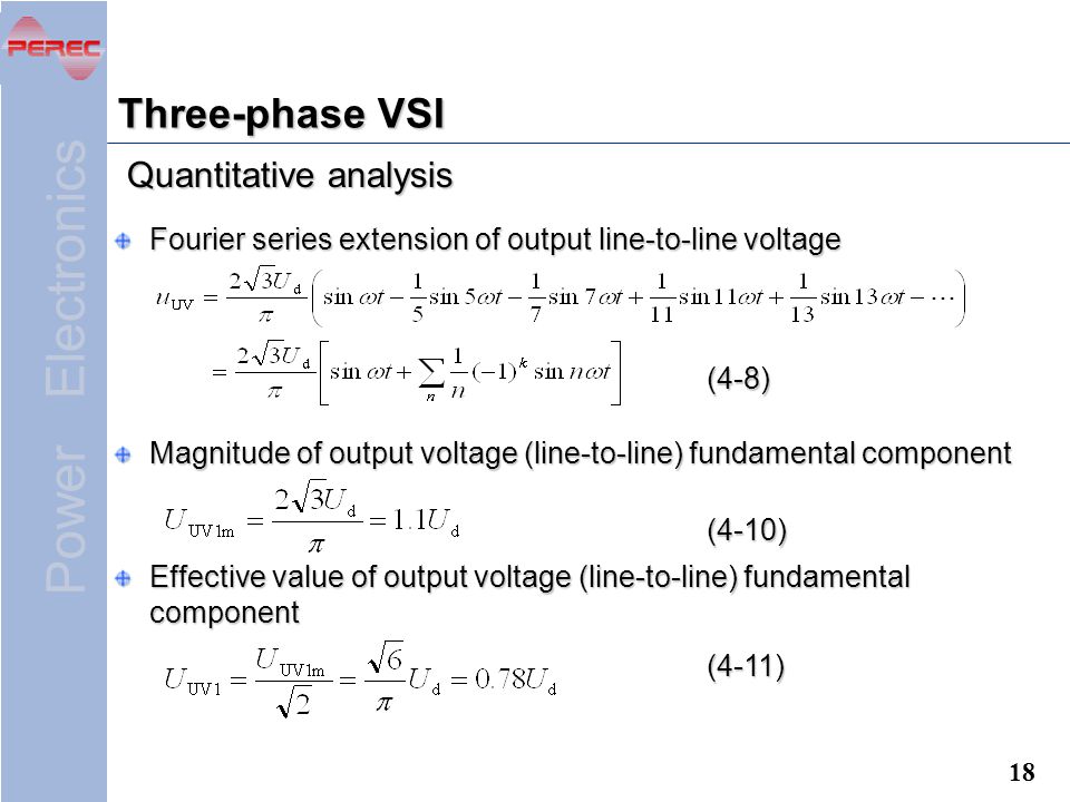
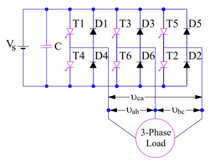
Three Phase Bridge Inverter Explained - Electrical Concepts

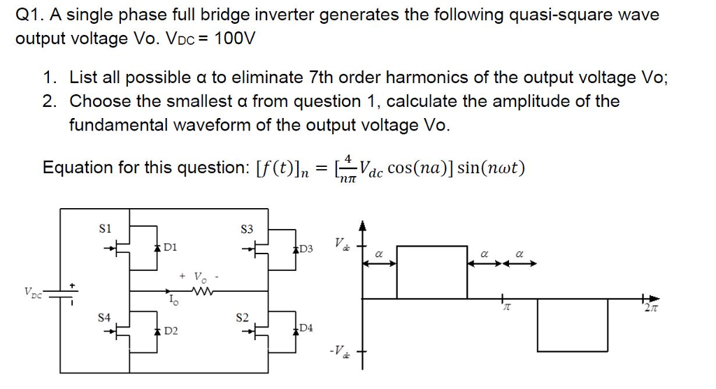
Solved A single phase full bridge inverter generates the | Chegg.com

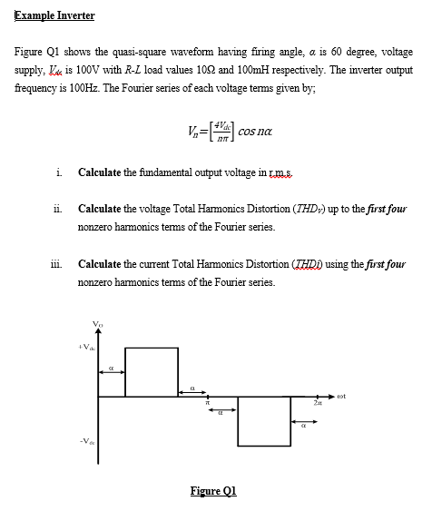
Solved Example Inverter Figure Q1 shows the quasi-square | Chegg.com

Calculate the output voltage and the current IDS flowing between Vdd and  Vss when the input to the CMOS inverter in Fig. 9.11 is 2.5V. Assume that  KN=KP=128 μA V^-2. | Holooly.com
Calculate the output voltage and the current IDS flowing between Vdd and Vss when the input to the CMOS inverter in Fig. 9.11 is 2.5V. Assume that KN=KP=128 μA V^-2. | Holooly.com
E-Learning Power Electronics

Average-value DC Voltage to three-phase AC voltage converter with fixed  power loss - MATLAB
Average-value DC Voltage to three-phase AC voltage converter with fixed power loss - MATLAB

Three phase inverters

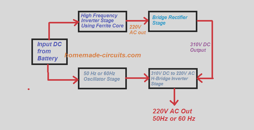
5kva Ferrite Core Inverter Circuit - Full Working Diagram with Calculation  Details - Homemade Circuit Projects
5kva Ferrite Core Inverter Circuit - Full Working Diagram with Calculation Details - Homemade Circuit Projects
EENG441 Solved Problems 2.

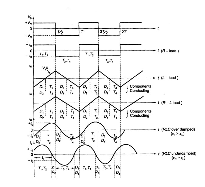
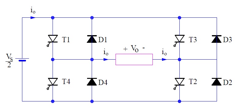
Single Phase Full Bridge Inverter: Circuit, operation and waveforms –  EEEbooks4U
Single Phase Full Bridge Inverter: Circuit, operation and waveforms – EEEbooks4U

Phase shift, d, between inverter output voltage, V inv , and grid... |  Download Scientific Diagram
Phase shift, d, between inverter output voltage, V inv , and grid... | Download Scientific Diagram

a). Inverter Output Voltage for RL Load | Download Scientific Diagram

measurement of output impedance of a CMOS inverter - Electrical Engineering  Stack Exchange
measurement of output impedance of a CMOS inverter - Electrical Engineering Stack Exchange

PULSE WIDTH MODULATED INVERTER

SIMULATION AND MODELING OF SINGLE PHASE DC (current source inverter). Here  we are using VSI. A
SIMULATION AND MODELING OF SINGLE PHASE DC (current source inverter). Here we are using VSI. A

Calculation of the motor input voltage as an inverter output voltage. |  Download Scientific Diagram
Calculation of the motor input voltage as an inverter output voltage. | Download Scientific Diagram

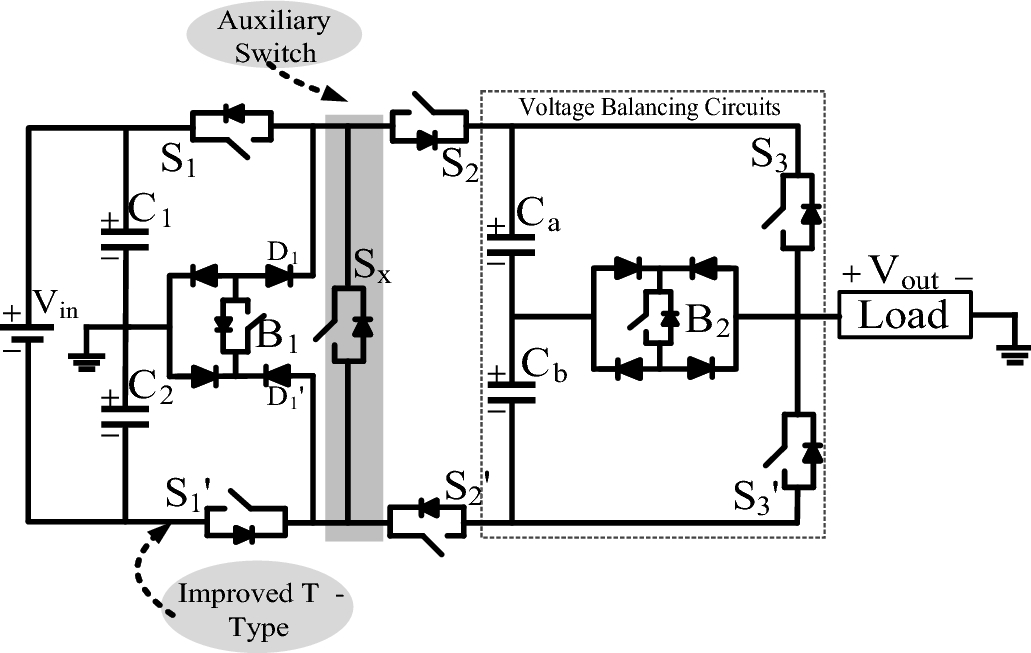
Experimental validation of new self-voltage balanced 9L-ANPC inverter for  photovoltaic applications | Scientific Reports
Experimental validation of new self-voltage balanced 9L-ANPC inverter for photovoltaic applications | Scientific Reports

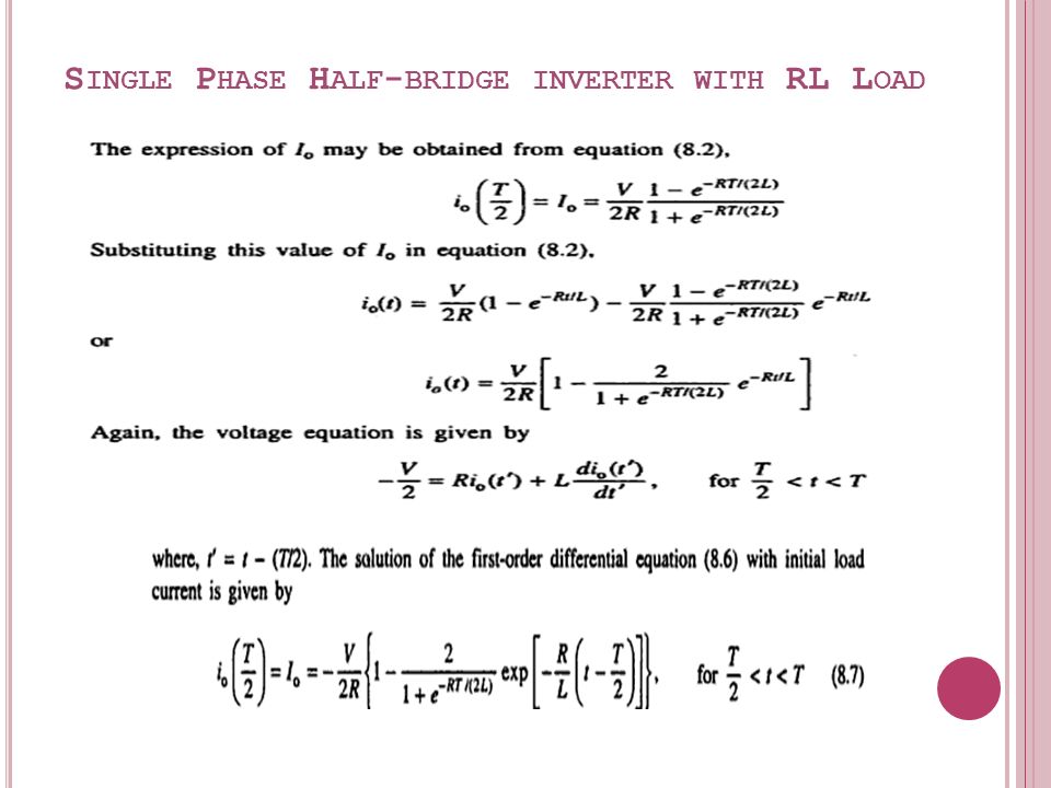
Single Phase Full Bridge Inverter Explained - Electrical Concepts

Calculation of the inverter hardware output voltage THD (4.43%) using... |  Download Scientific Diagram
Calculation of the inverter hardware output voltage THD (4.43%) using... | Download Scientific Diagram